Duplicate

Lecture 7 | Camera Model

수강 일자
2023/02/26

Overview: Camera Projections

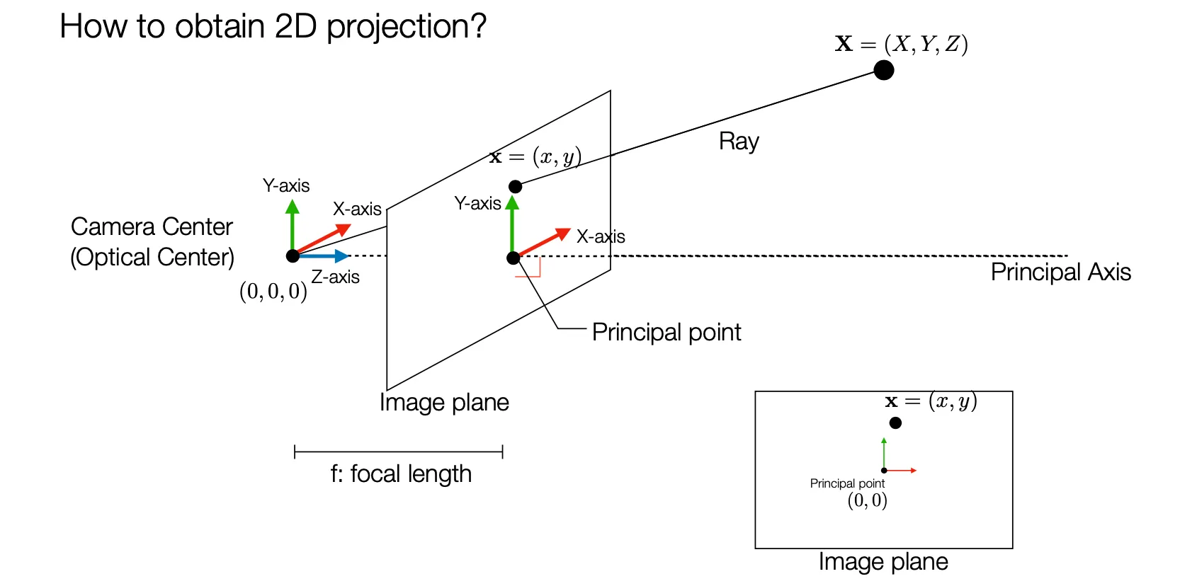
일반적으로 상은 Camera Center (Pinhole) 뒤 쪽에 focal length ff 만큼 거리의 위치에 생기지만, 편의를 위해서 Camera Center 앞 쪽 ff 만큼 거리에 그리는 경우가 많음.
Image Plane 과 수직인 axis 를 Principle Axis 로, 그 교점을 Principle Point 라고 부름.
Camera Center 와 물체의 특정 위치를 잇는 선을 3D Ray 라고 하고 이는 Image Plane 에서 상으로 맺힘.
같은 3D Ray 위에 있는 점은 Image Plane 에서 같은 위치에 상으로 맺힘.
2D Image Plane 위의 점 x=(x,y){\rm x} = (x,y) 가 3D Point X=(X,Y,Z){\rm X} = (X,Y,Z) 와 대응된다면, 다음이 성립함.
f:y=Z:Yy=fYZf:x=Z:Xx=fXZ(X,Y.Z)T(fXZ,fYZ)=(fX,fY,Z)f:y = Z:Y \to y = f\frac{Y}{Z} \\ f:x = Z:X \to x = f\frac{X}{Z} \\ \quad \\ (X,Y.Z)^T \to (f\frac{X}{Z}, f\frac{Y}{Z}) = (fX,fY,Z)
3D coordinates 에 scalar kk 가 곱해지더라도 동일한 2D Plane 상의 점에 대응됨을 알 수 있음.

Camera Intrinsic Parameters

(XYZ1)(fXfYZ)=[f0f010](XYZ1)\begin{pmatrix} X \\ Y \\ Z \\ 1 \\ \end{pmatrix} \to \begin{pmatrix} fX \\ fY \\ Z \\ \end{pmatrix} = \begin{bmatrix} f & & & 0 \\ & f & & 0\\ & & 1 & 0 \\ \end{bmatrix} \begin{pmatrix} X \\ Y \\ Z \\ 1 \\ \end{pmatrix}
3D Point 를 Homogeneous Coordinate 로 나타낸 것을 2D Point 를 Homogeneous Coordinate 로 나타낸 것으로 변환하기 위해서 위와 같이 focal length ff 를 기반으로 3×43\times4 matrix 를 구성할 수 있음.
3×43\times4 matrix 는 다음과 같이 표현할 수 있음.
[f0f010]=[ff1][101010]=K[I0]\begin{bmatrix} f & & & 0 \\ & f & & 0\\ & & 1 & 0 \\ \end{bmatrix} = \begin{bmatrix} f & & \\ & f & \\ & & 1 \\ \end{bmatrix} \begin{bmatrix} 1 & & & 0 \\ & 1 & & 0\\ & & 1 &0 \\ \end{bmatrix} = K[{{\rm{I}}}| 0]
이 분리된 matrix 의 앞을 Intrinsic Parameter (K)(K), 뒤를 Extrinsic Parameter ([IO])([I|O])라고 부름.
일반적으로 Image Plane 위의 origin 은 중심점이 아니라, 좌 하단의 점 등 corner point 이기 마련임. 이에 대한 보정은 다음과 같이 할 수 있음.
(X,Y,Z)T(fXZ+px,fYZ+py)(XYZ1)(fX+ZpxfY+ZpyZ)=[fpx0fpy010](XYZ1)=[fpxfpy1][101010](XYZ1)(X,Y,Z)^T \to (f\frac{X}{Z} + p_x, f\frac{Y}{Z}+p_y) \\ \begin{align*} \begin{pmatrix} X \\ Y \\ Z \\ 1 \\ \end{pmatrix} \to \begin{pmatrix} fX + Zp_x\\ fY + Zp_y \\ Z \\ \end{pmatrix} &= \begin{bmatrix} f & & p_x & 0 \\ & f & p_y & 0\\ & & 1 & 0 \\ \end{bmatrix} \begin{pmatrix} X \\ Y \\ Z \\ 1 \\ \end{pmatrix} \\ &= \begin{bmatrix} f & & p_x \\ & f & p_y\\ & & 1 \\ \end{bmatrix} \begin{bmatrix} 1 & & & 0 \\ & 1 & & 0\\ & & 1 &0 \\ \end{bmatrix} \begin{pmatrix} X \\ Y \\ Z \\ 1 \\ \end{pmatrix} \end{align*}
px,pyp_x, p_y 는 중심점으로부터 Priniciple Point 까지의 보정에 필요한 offset 을 의미함.
Intrinsic Parameter (K)(K)px,pyp_x,p_y 항목이 추가됨.
3D Coordinate 의 측정 physical unit 을 pixel unit 으로 바꾸기 위해 다음과 같은 보정을 할 수 있음.
K=[fpxfpy1]K=[αxx0αyy01]K= \begin{bmatrix} f & & p_x \\ & f & p_y \\ & & 1 \end{bmatrix} \to K= \begin{bmatrix} \alpha_x & & x_0 \\ & \alpha_y & y_0 \\ & & 1 \end{bmatrix}
αx=mxf,αy=myf\alpha_x = m_xf, \alpha_y = m_yf
mx,mym_x, m_y 는 physical pixel 을 pixel unit 으로 바꾸기 위한 scaling factor 임.
x,yx, y 방향의 scaling factor 가 다른 것은 non-squared pixels 를 다루는 경우를 일반화 한 것임.
더 일반적으로는, pixel 이 perpendicular 하지 않은 경우 (e.g. 평행사변형 픽셀) 를 대응하기 위해 Skew Parameter ss 를 도입해 다음과 같이 Intrinsic Parameter 를 구축할 수 있음
K=[αxx0αyy01]K=[αxsx0αyy01]K=\begin{bmatrix} \alpha_x & & x_0 \\ & \alpha_y & y_0 \\ & & 1 \end{bmatrix} \to K = \begin{bmatrix} \alpha_x & s& x_0 \\ & \alpha_y & y_0 \\ & & 1 \end{bmatrix}

Focal Length

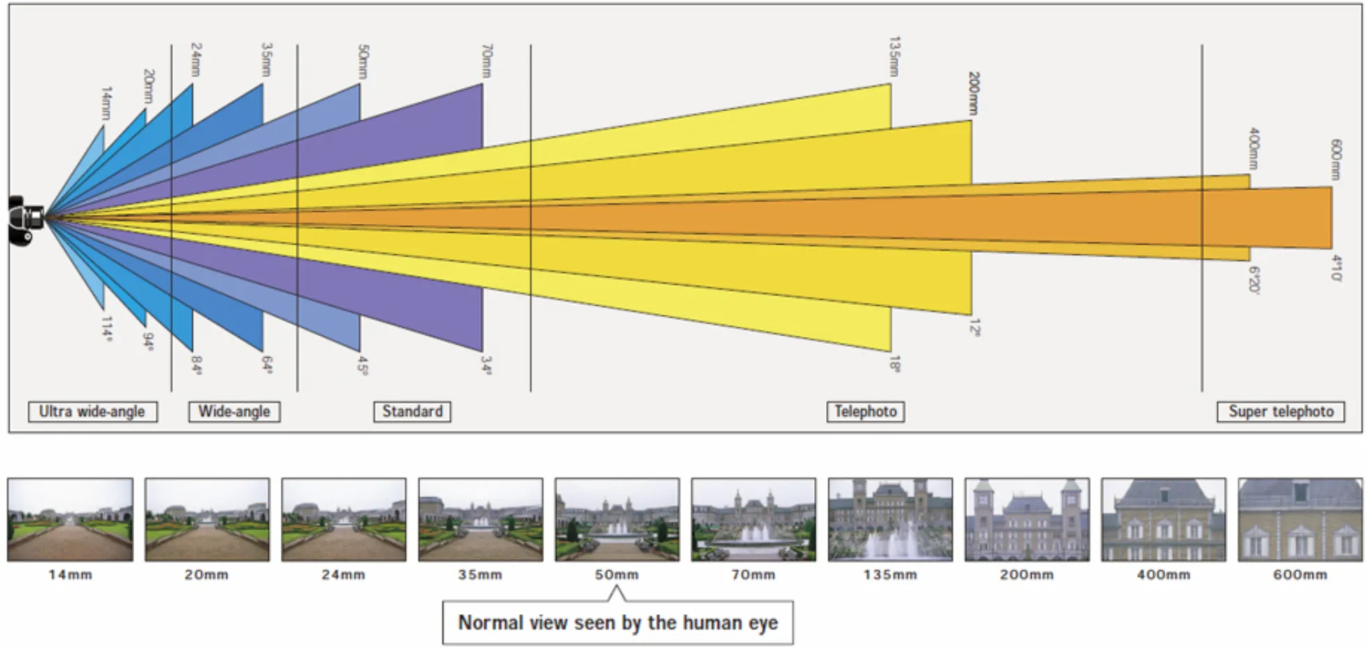
낮은 focal length 를 가지면 wide view 를 가지고 있지만, 확대의 비율이 적음.
동일한 크기의 Image Plane 을 가정했을 때 볼 수 있는 범위가 넓음.
높은 focal length 를 가지면 narrow view 를 가지고 있지만, 확대의 비율이 큼.
동일한 크기의 Image Plane 을 가정했을 때 볼 수 있는 범위가 좁음.

Extrinsic Parameters

간단한 상황에서는 Camera Center 를 (0,0,0)(0,0,0) 으로 가정했지만, 실제에서는 그렇지 않음.
World Coordinate 를 Camer Coordinate 로 변환하는 과정이 Extrinsic Parameter 에 의해 진행됨.
이러한 좌표계 변환은 rotation matrix RR 과 translation t{\rm t} 에 의해 다음과 같이 나타낼 수 있음.
Xcam=RXworld+t=[Rt][Xworld1]{\rm X}_{\rm cam} = R{\rm X_{world}} + {\rm t} = \begin{bmatrix} R | {\rm t} \end{bmatrix} \begin{bmatrix} {\rm X_{world}} \\ 1 \end{bmatrix}
위 변환을 이용해 기존의 변환된 Camera Center 가 (0,0,0)T(0,0,0)^T 이 되도록 하기 위해 다음과 같은 식을 세울 수 있음.
Ccam=(0,0,0)T=RCworld+tRCworld=tCworld=RTt{\rm C_{cam}} = (0,0,0)^T = R{\rm C_{world}} + {\rm t} \\ -R{\rm C_{world}} = {\rm t} \\ {\rm C_{world}} = -R^T{\rm t}
이 식을 활용해 R,tR, {\rm t} 를 구할 수 있음.
최종적으로는 World Coordinate 를 Camera Coordinate 로 변환한 뒤에 Intrinsic Parameter 를 적용해 Camera System 을 구축함.
x=PXworld=K[Rt]Xworld{\rm x} = {\rm PX_{world}} = K[R|{ \rm t}]{\rm X_{world}}
Camera Calibration 은 K,R,tK,R,{\rm t} 를 구하는 과정임.

Finite Projective Cameras

P=K[Rt]=KR[ICworld]{\rm P} = K[R | {\rm t}] = KR[I | -{\rm C_{world}}]
PP 는 총 11DoF
KK 는 5DoF: αx,αy,s,x0,y0\alpha_x, \alpha_y, s, x_0, y_0
RR 은 3DoF: Roll, Pitch, Yaw
t{\rm t} 는 3DoF: tx,ty,tzt_x, t_y, t_z
Finite Projective Camera 는 다음과 같이 정의됨.
모든 좌측 3×33\times3 이 Non-Singular 인 3×43\times 4 matrix 는 Projective Camera 의 Camera Matrix 가 될 수 있음.
Cworld{\rm C_{world}} 의 projection 인 Ccam{\rm C_{cam}} 은 의도대로 (0,0,0)T(0,0,0)^T 임.